Blog - A Guide to Syringe Filters and How to Use Them
Mar 04, 2018 · 1.Get the most appropriate filter to use. 2.Draw 1ml of air followed by your sample in a sterile syringe. 3.Eject 1ml of the sample in a waste container. 4.Eject the rest of the sample in a clean vial for storage. 5.Push the air you initially drew into the same vial. This step will push out the remaining fluid and will reduce the held up volume.
ABCD Matrix | OptoWiki Knowledge Base
Blue Shift of Bandpass Filters; Bokeh; Blog. Can I increase the DOF by changing the focal length, if FOV and brightness are constant? Little siblings: s-Mount lenses as replacement for c-mount lenses; Comparison: c-mount lenses vs. s-mount lenses (M12x0.5) Book. Chapter 01: Introduction; Chapter 02: Basics
Ray Transfer Matrix Analysis & ABCD matrix Package
of using matrix method lies in the fact that the ray transfer matrix of a cascade of optical system is a product of the ray transfer matrices of the individual system.
Syringe Filters
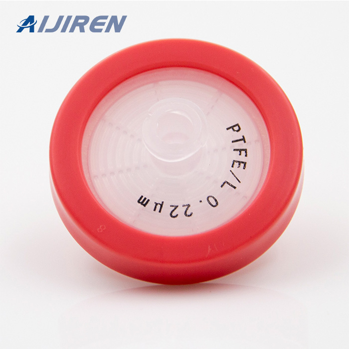
PTFE Syringe Filters. PTFE syringe filters are hydrophobic and chemically resistant to all solvents, acids, and bases. PTFE does not impart any extractables to the filtrate. It's an ideal material for transducer protectors because it blocks water vapor. PTFE is ideal for filtering and de-gassing chromatography solvents.
S-parameter and ABCD matrix - Forum for Electronics
May 01, 2008 · you are right about the mistake made by pozar. after correcting the mistake, i tried to simplified the equation, but it was really difficult, after long hours, i ended up with a power 5 equation of e^-gamma*L. which i believe is impossible to solve.
Syringe Filters - Sigma-Aldrich
Hold the syringe with the filter pointing up and “top off” by pushing a few drops through the filter. Place the filter tip over the collection container and push the sample through a syringe filter by applying gentle positive pressure. To purge the syringe filter and maximize sample throughput, remove the filter from the syringe and draw air into the syringe. Then reattach the filter and push the plunger to force some of the air through the filter.
How to Select a Syringe Filter and How to Use it? (2020 Guide)
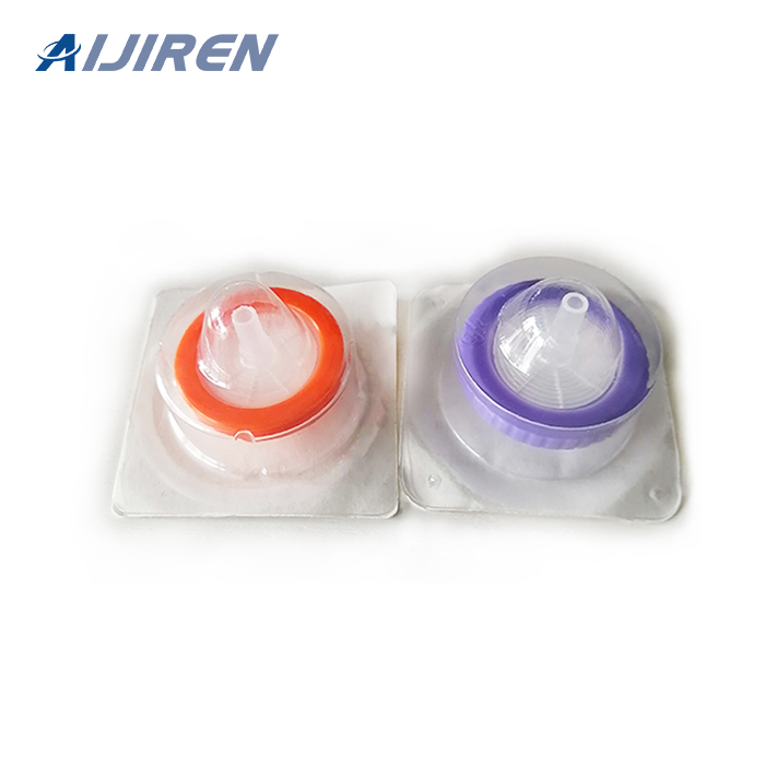
Feb 17, 2020 · Note: The individually packed sterile syringe filter can be held in the original package to minimize contamination while attaching the syringe. Step 3: Secure the Syringe Filter. Secure the syringe filter using a clockwise motion with luer-lock syringe. DO NOT overtighten. Step 4: Filter the Solution. Hold the assembled syringe and filter it upright.
Syringe Filters for Aqueous Solutions
The pore size of your syringe filter is determined by the size of the particles you need to filter out of your aqueous solution. Syringe filters for aqueous solutions are available in these pore sizes: 0.05 µm, 0.10 µm, 0.22 µm, 0.45 µm, 0.70 µm, 0.80 µm, 1 µm, 3 µm, 5 µm, and 10 µm . As a guide, the finer the pore, the more pressure
Syringe Filters - Pall Corporation
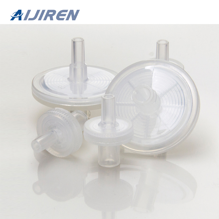
Syringe filters are single use, self contained, filtration devices that are typically used to remove contaminating particulate from liquids or gasses. When selecting the correct syringe filter for an application there are a number of factors to consider, these include: Filter and housing materials. Pore size. Effective filtration area.
syringe filter – syringefilter.com
0.22 micron 0.45 micron syringe filters nylon Nylon PTFE PES GF glass fiber 13mm 30mm 25mm PVDF Polyvinylidene Fluoride Cellulose Acetate Filter syringe filter
Lecture # 11: Transmission (ABCD) Matrix
Introduction •Z parameters are useful for series connected networks •Y parameters are useful for parallel connected networks •S parameters are useful for describing
Gaussian Beam Propagation with ABCD Matrices - Optics Girl
Case 1: For propagation in free space over a distance d, then clearly if q ( z 1) = q 1, then q ( z 2) = q 2 = q 1 + d. We can see this because the effect of the propagation in the distance term would just be to add a distance d. This can be written as: Case 2: With propagation through a thin lens, the lens will transform the wavefront radius R
Using A D Matrices to find the position of a Gaussian beam waist
and final angle (θ, θ). A four element matrix can then describe how the new position and angle are derived from the initial values. (????′ ????′)=( # $ % &)(???? ????) For example, a simple space of length d has a ray diagram like: In this case, the relation between the input and output positions and angles are described by the following
ABCD matrix, explained by RP Photonics Encyclopedia; ray
Originally, the concept was developed in geometrical optics for calculating the propagation of light rays with some transverse offset r and offset angle θ from a reference axis (Figure 1).
Ray transfer matrix analysis - Wikipedia
The ray tracing technique is based on two reference planes, called the input and output planes, each perpendicular to the optical axis of the system. At any point along the optical train an optical axis is defined corresponding to a central ray; that central ray is propagated to define the optical axis further in the optical train which need not be in the same physical direction (such as when
-
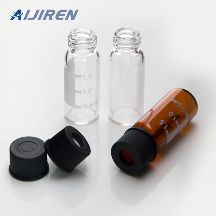
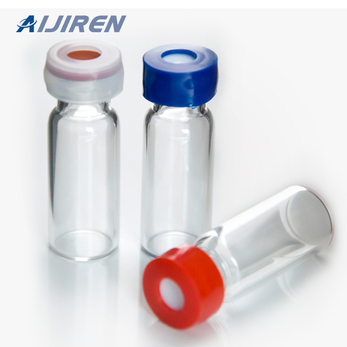
Material: USP Type 1, Class A, 33 Borosilicate Glass
Volume: 2ml (standard volume) 1.5ml(actual volume)
Application: HPLC and GC system
Dimensions: 11.6 x 32mm
Neck Diameter: 8mm
Qty/Pack: 100pcs/pack
Payment: T/T
MOQ: 1pack1.5 ML/2ML 8-425 Screw Neck Autosampler Vials ND8 -
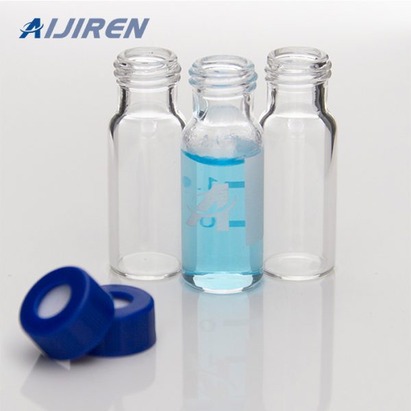
Material: USP Type 1, Class A, 33 Borosilicate Glass
Volume: 2ml (standard volume) 1.5ml(actual volume)
Application: HPLC and GC system
Dimensions: 11.6 x 32mm
Neck Diameter: 9mm
Qty/Pack: 100pcs/pack
Payment: T/T
MOQ: 1pack1.5ml 9mm Short Thread Autosampler Vials ND9 -
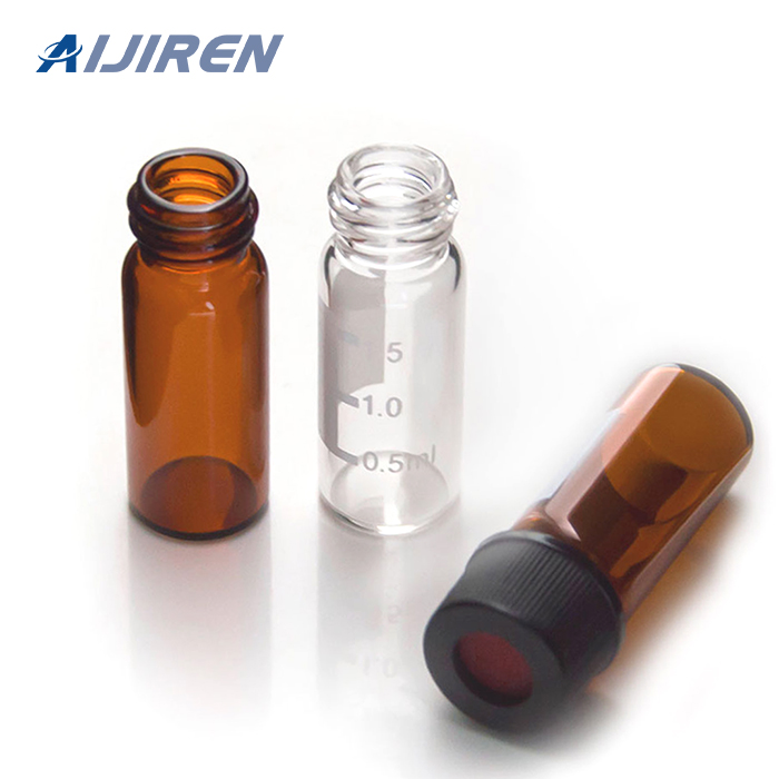
Material: USP Type 1, Class A, 33 Borosilicate Glass
Volume: 2ml (standard volume) 1.5ml(actual volume)
Application: HPLC and GC system
Dimensions: 11.6 x 32mm
Neck Diameter: 10mm
Qty/Pack: 100pcs/pack
Payment: T/T
MOQ: 1pack1.5ml 10-425 Screw Autosampler Vials ND10 -
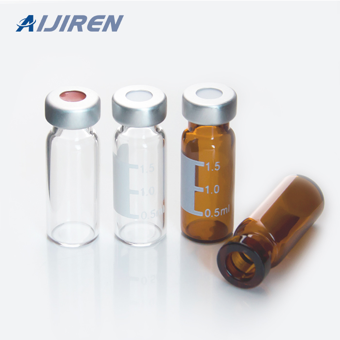
Material: USP Type 1, Class A, 33 Borosilicate Glass
Volume: 2ml (standard volume) 1.5ml(actual volume)
Application: HPLC and GC system
Dimensions: 11.6 x 32mm
Neck Diameter: 11mm
Qty/Pack: 100pcs/pack
Payment: T/T
MOQ: 1pack1.5mL 11mm Crimp Ring Autosampler Vial ND11
